Ladder Diagram For Pump Control What Is Ladder Diagram?
Plc level logic programming instrumentationtools programmable schematics danelectro discharge plcs activated controllers Plc program for temperature control using thermostat instrumentation tools Plc program for temperature control using thermostat
Motor Control Circuit Wiring - Inst Tools
Motor control ladder diagram simulator Plc programming basics siemens s7 originally method relay programmable docume controllers instrumentation aj Solved design a ladder diagram to control the level of a
Plc ladder logic motor phase diagram control start stop programming using reverse forward wire three siemens asynchronous tia wiring
[diagram] motor control circuit ladder diagramPlc normally circuit pressed instrumentationtools because Basics of ladder diagram in plc programmingDraw ladder diagram for this circuit and explain.
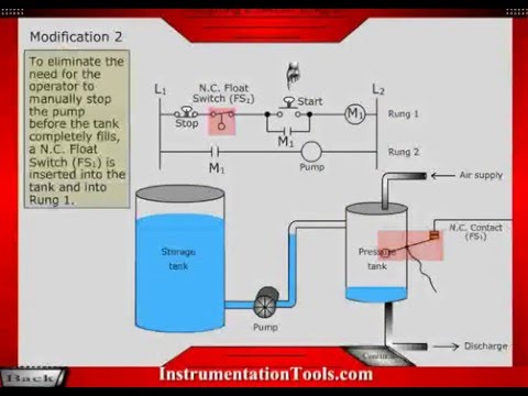
Download plc programming languages ladder diagram bookWhat is ladder diagram? Sample of a ladder logic diagram for a water pumping system.Motor control circuit wiring diagram ladder simple system circuits components instrumentation where off instrumentationtools tools showing.

Solved use the worksheet "pump circuit ladder diagram"
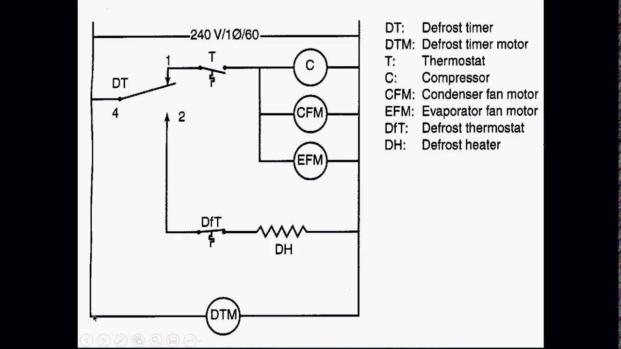
Plc control temperature thermostat program using ladder logic programming heaters diagram instrumentationtools system circuit electrical three components projects electronic operation4 design and schematic drawing of a ladder diagram Motor control schematics ladder diagramSolved draw a ladder diagram for a pumping system where the.
Engineering of water systems – water well journalLadder diagram basics #1 Ladder diagramsMotor control ladder diagram software.

Solved 1- draw a ladder diagram for a pumping system where
3 wire start stop ladder diagramLadder diagram part 01 Week 10: control and instrumentation systemsPumping ladder.
Motor control circuit wiringLadder logic for pump control Ladder logic hvac schematic relay plc conditioning basic circuit elevator manufacturing shown programmableLadder diagram for the electrical control system 4. results and.

Ladder diagram of automation pump
[diagram] parts of ladder diagramDesign a ladder diagram for a pumping system, as Plc temperature thermostat programming diagrama diagrams heaters instrumentationtools conveyor temperatura fuerza electrica mechanical dummies electricidad used schematics programmable arduino eléctricoPlc water level logic.
A) design a ladder diagram for a pumping system whereLadder diagram control circuit Plc ladder logic drawingLogic pump ladder.

Ladder diagram electrical symbols basics sponsored links
Plc program for motor starter instrumentation toolsDiagram solved problem pumping ladder draw system transcribed text been show has Solved draw a ladder diagram for a pumping system where theLadder diagrams.
.


Solved Draw a ladder diagram for a pumping system where the | Chegg.com
Ladder Diagrams - YouTube
Basics of Ladder Diagram in PLC Programming | Instrumentation Tools
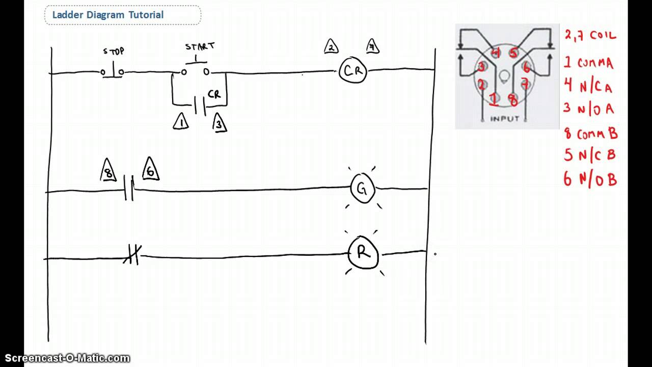
Ladder Diagram Basics #1 - YouTube

LADDER DIAGRAM OF AUTOMATION PUMP - LEKULE

PLC Program for Temperature Control using Thermostat Instrumentation Tools

Motor Control Circuit Wiring - Inst Tools